 stereo recap
Realistic STA-2100D Restore
While cleaning house, my father in-law had a vintage stereo that he didn’t want anymore. I tossed it in the back of the car and took it home. On further research, it turns out it is probably the best stereo that Realistic ever made and a highly collectable.
The main restoration other than cleaning that vintage stereos need is replacement of all the electrolytic capacitors (know as a recap). Electrolytic capacitors eventually leak or degrade their electrolyte.
I purchased a 2100D capacitor kit from ebay vendor hifiaudio-. He also supplied links to both the operations and repair manuals. He supplied a work plan on how to do the re-cap but tdid not include any instructions on the physical layout or disassembly. Most information I found online had full removal of the boards which involves much more rewiring than necessary.
This is a detailed instruction manual on how to rebuild a STA-2100D with minimal rewiring:
Disassembly:
There are good instructions in the repair manual on how to remove the case and expose the bare chassis which I won’t cover here. Thoroughly clean out case by gentle use of a vacuum and compressed air.
Tools:
- A quality fine tip soldering iron – I use a Hakko FX-888D
- 0.32-0.4 mm flux core solder – Everyone has a favorite brand, I use MG or Kester.
- Solder wick – NTE – You will use 10+ feet of wick
- Flush cutters – Hakko CHP-170
- Several sizes of needle nose pliers
- #2 Philips Head Screwdriver
- Several sizes of straight screwdrivers
- A 2mm hex wrench
- A good aim able LED light
- Electronic Silicone for remounting thermistors
- Deoxit D5 Electronic Cleaner
- Sprayway Glass Cleaner
You will be working around leaded solder from the board as well as fumes from new solder. Work in a well ventilated area, ideally with a solder fume extractor.
Work Process:
Take plenty of pictures before disconnecting anything!
Have a work area that you can keep undisturbed for the duration of the project.
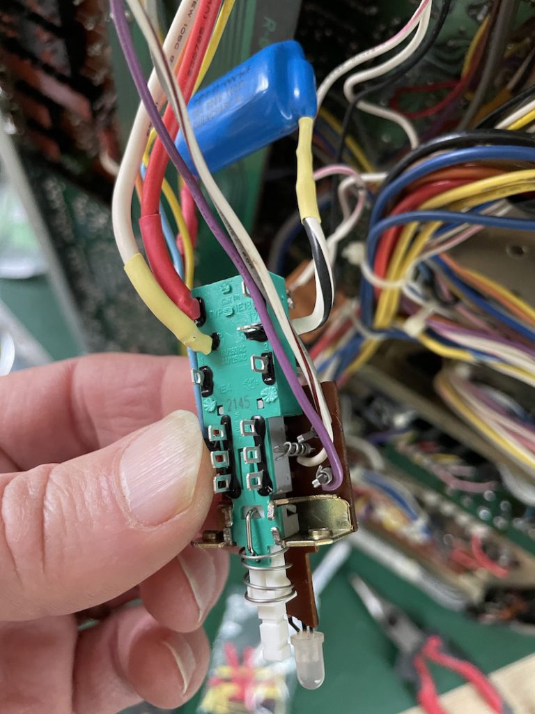
Work slowly, take breaks… the work is intense and you will make mistakes if tired. Reversed polarity on an electrolytic cap will cause it to explode.
Be methodical:
- Remove a single component at a time
- Identify the component number and find the replacement component before starting
- Note polarity of the PCB marking, the circuit diagram and the component as you are removing
- Note polarity of the PCB marking, the circuit diagram and the new component as you are replacing
- Catch every snipped wire. If you can’t find it, stop and find it!
- Cross things off as you do them
- Pay close attention to any broken or unwrapped wires
- Confirm the entire board before moving on
- Wait until the end to replace tywraps
Layout:

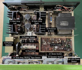
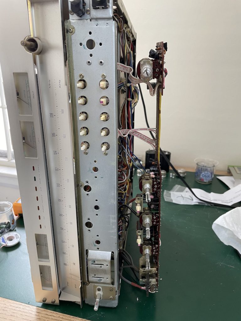
Both the repair manual and the instruction in the recap kit lack any orientation to where boards are found in the chassis. This is a good top down map. Stereo front is down in this picture. When I refer to things front/rear/left/right it’s from this perspective. The numbers here refer to the repair manual PCB references. Note, only the boards needing cap repair are listed and I only describe what is necessary to access them to do the recap. I left as much in-situ as possible without disconnecting wires. The step numbering in the recap kit, does not correspond to the board numbering!
Detailed repair notes:
Rear:
- Main Filter Caps
- 15/16 – Main Amps
- 18 – Protector & Meter
- 23 – Relay
Front:
- 12 – Front End
- 13 – PreAmp Selector
- 14 – Tone Amp, Muting, Tape Switch
- 17 – I/F & Dolby
- 18 – Power Supply
- 20 – Speaker Switch – Does not require recap
- 21 – Mode Switch – Does not require recap
- 26 – LED Power Switch
Main Filter Caps
The largest caps C1405/C1406 in the chassis are the main filter caps. The ones supplied in the kit are smaller diameter than the originals and required me to CNC machine adapter rings to fit the original mounts. I also tried some 3D-printed adapters, but I felt using bakelite material was going to be more temperature resistant and in the spirit of the vintage amp.
This is the only step where you might need a more powerful solder sucker and iron. Patience and solder wick got it done for me.
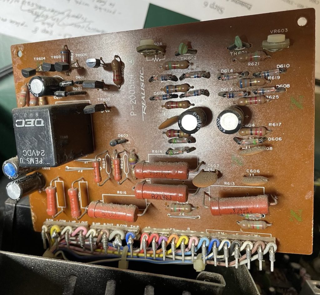
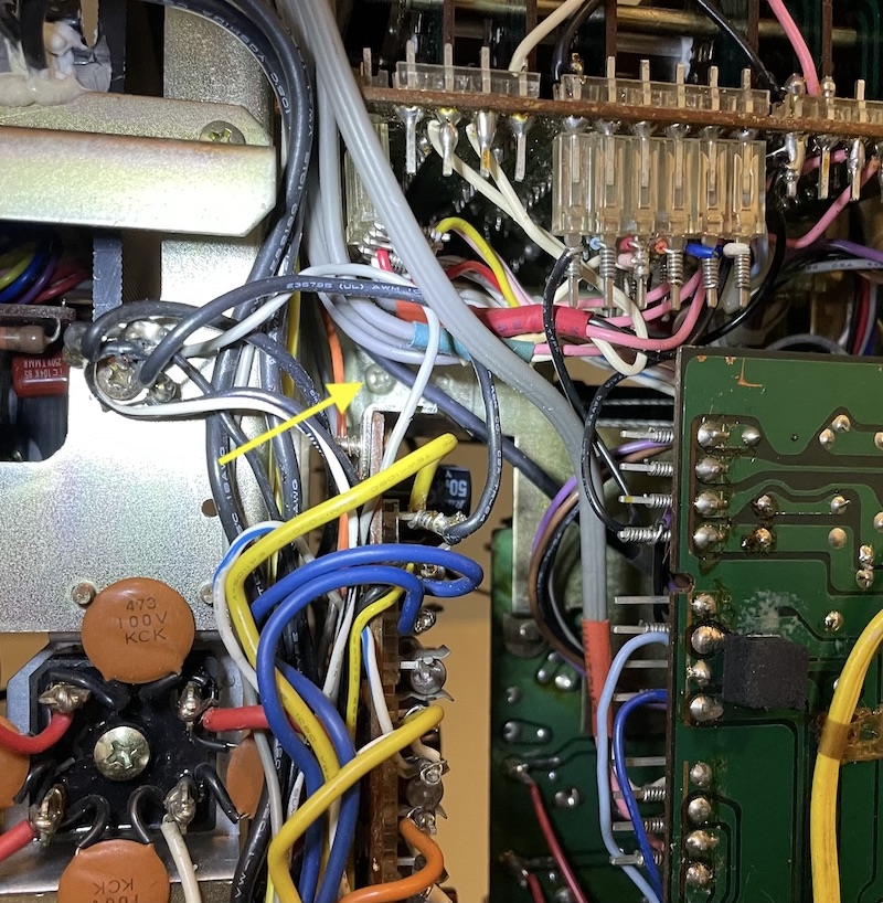
15/16 – Main Amps
The Main Amps are easily removed from the chassis to work on.
Take pictures before you remove plugs! Don’t assume my pictures are the same wire colors as yours.
Place the chassis on the right hand side, so both bottom and top are accessible.
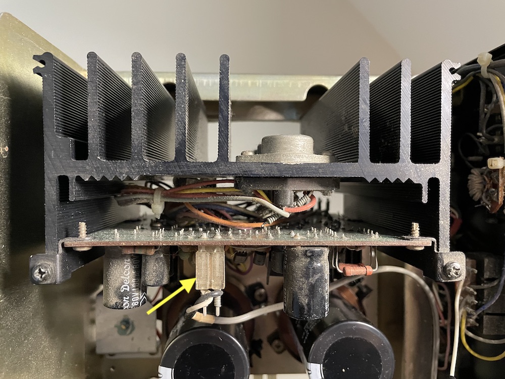
From the top: Remove the white pre-amp plug [Yellow Arrow] from the top of the board. For the right amp, remove the screws holding the standoff wires for the antenna lead.
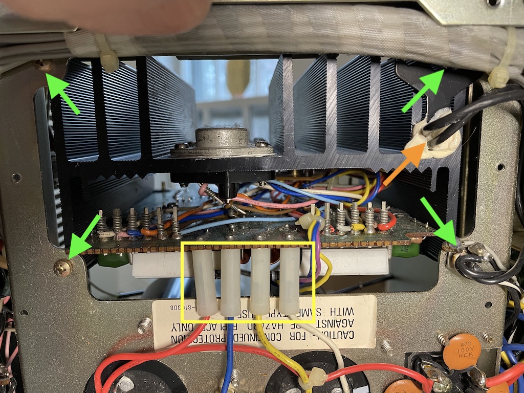
From the bottom: Remove the 4 connections [Yellow Box]. Remove the screw holding the thermistor mount down [Top right in picture above]. Remove the thermistor [Orange arrow] carefully with an hobby knife. Remove the 3 remaining screws [Green arrows]. Note you may have to carefully move wires to get to the screws. Remove the main Amp from the top.
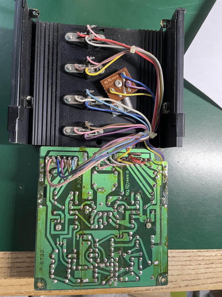
With the Main Amp out of the chassis, remove the 2 screws securing the board to the heatsink bracket. Slide the board up and away from the heatsink brackets and rotate 180 degrees “open” to reveal the solder side of the board.
RECAP the board according to steps in the kit. Replacement is the reverse of removal.
REPEAT for the RIGHT AMP which is a mirror image of the LEFT AMP.
23 Relay PCB
There are only 2 caps near the top of this board and it is possible to do in place.
18 Protector and Meter
You can do this insitu from the top.
Remove the two screws at the top of the board and move the board up and out of the lower slots. Carefully guide the wires (you may have to cut tywraps) and move the board up until fully exposed.
RECAP the board according to steps in the kit. Replacement is the reverse of removal.
This completes the rear section
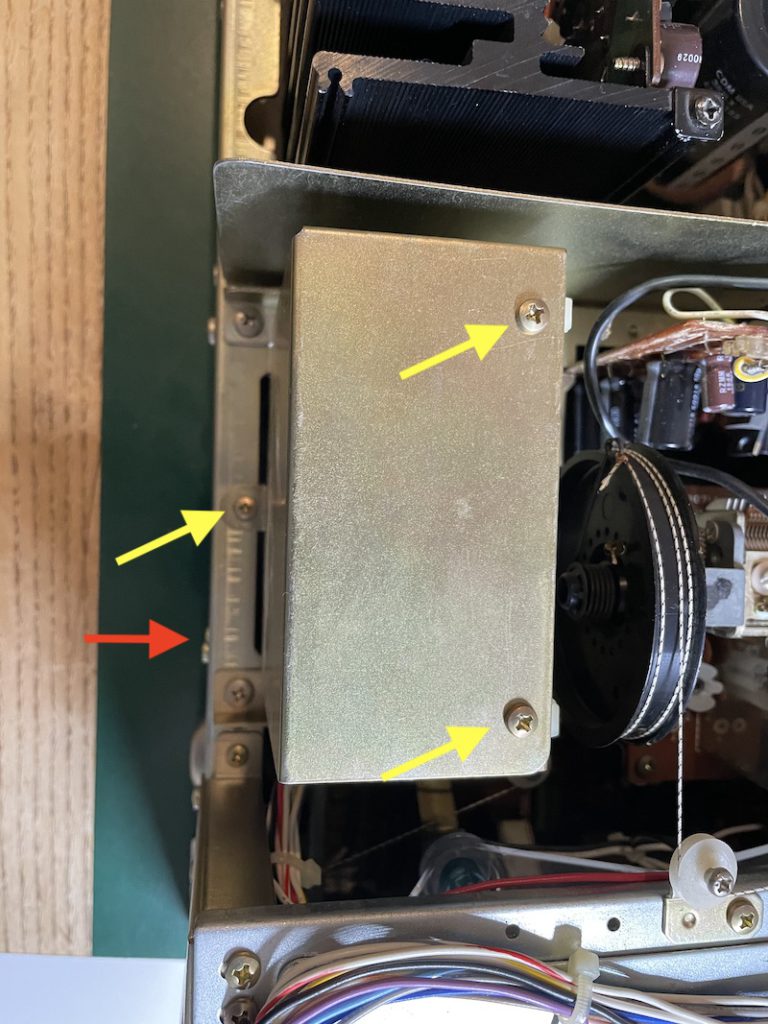
19 Power Supply
From the bottom: Remove the two screws holding the board brackets to the chassis [Yellow Arrows below]
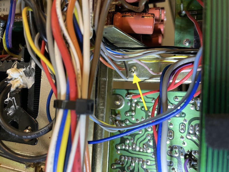
Remove the ground from the Left Main Amp screw [See Main Amp Bottom Picture, lower right green arrow]. Carefully remove tywraps and guide board out bottom of chassis rotating 90 degrees to expose board.
RECAP the board according to steps in the kit. C721 was missing from the Recap Kit. Replacement is the reverse of removal.
Consider doing board 17 IF + Dolby before replacing board 19.
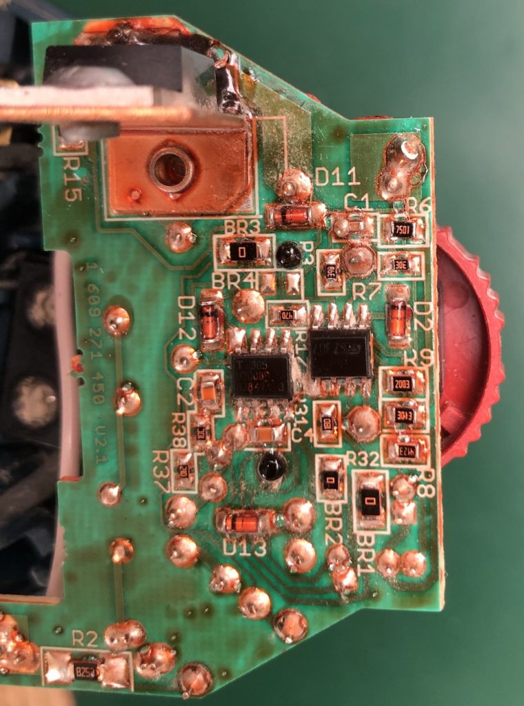
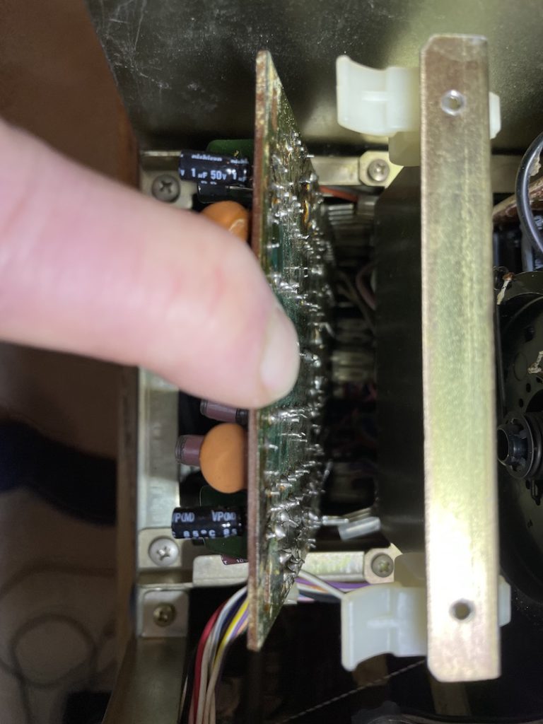
17 IF + Dolby
From the top: Remove the 6 short screws holding the board to the chassis. Carefully rotate rear edge of board up. Maneuver front edge of board slightly to the rear to clear chassis. You may have to remove tywraps to allow enough movement.
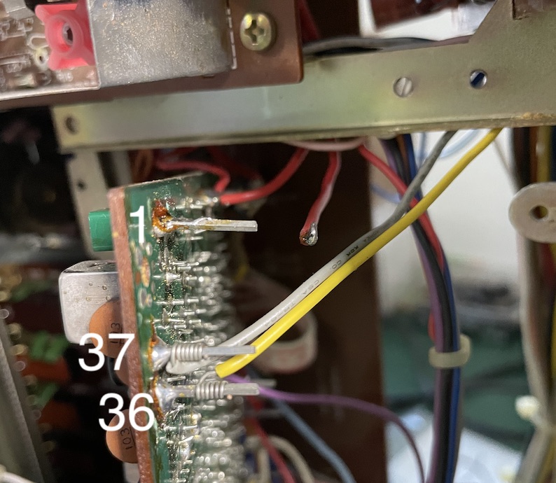
Unsolder the red wire going to terminal 1 near the left rear of the board near the C241 marking (C241 component was missing). Unwrap the yellow terminal 36 and gray terminal 37 wires.
Rotate the board nearly 90 degrees – right side will be freer than left – Stabilize the board as best you can.
RECAP the board according to steps in the kit. C226 was missing from the kit, 47uf 16v. As you maneuver the board back in the chassis, rewrap or solder yellow to terminal 36 and gray to terminal 37 wires. Resolder red wire to terminal 1. Replacement is the reverse of removal.
Check carefully for any broken wire wraps. Reroute wires
14 Tone Amp, Muting, Tape
This board contains most of the knobs and switches.
From the front: Remove the tuner knob with a 2mm hex wrench. Remove all the other knobs and switches. The buttons are attached to the face plate and do not come off. Remove two screws on each side of the face plate. Remove the 3 screws on the bottom of the face plate. Being careful of the tuner indicator, remove the faceplate.
From the front: Remove the hex nuts and washers from the bass-mid-treble potentiometers. Remove the hex nut and washer from the volume knob. Remove the screws from the tape and turnover switches.
With the unit on it’s left side, carefully slide the board back and down until separated from the unit. No wires need to be disconnected.
RECAP the board according to steps in the kit. C1005 is labeled incorrectly in the service manual circuit diagram, it is correct on the board.
Consider doing 13 Preamp, Selector Switch before replacing board. Replacement is the reverse of removal.
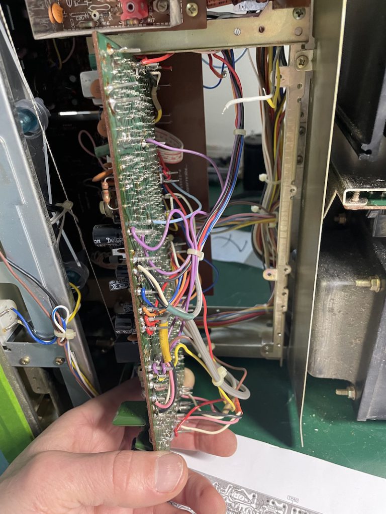
13 Preamp, Selector Switch
Turn the unit on its bottom with the left side facing you. Remove the 3 screws securing the metal shield [Yellow Arrows]. Remove the shield.
Unscrew the two screws securing the selector switch to the chassis [Red Arrow]. Unclip the two plastic clips securing the board. Carefully pull the top towards the left to expose the solder side of the board.
Remove the two plugs on the board to relieve pressure.
Guide lower plugs past edge of 14 Tone Amp board. I think I removed one of the plugs to allow further motion.
This is very tight to do this soldering. An angled soldering tip, good lighting and a head mounted magnifier will help. I skipped C310A/B as these were not electrolytic and almost impossible to reach. The polarity on C304A/B is incorrect in the service manual diagram but correct on the board. Negative is top lead.
Replacement is the reverse of removal.
Power Switch
Not part of the recap, but it is common for the power switches to arc and become very unreliable. They are easily replaceable when the unit is open. Remove the two screws from the front panel and pull the switch to the rear until it can be freed.
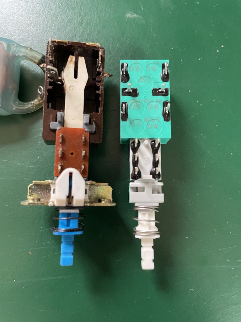
You can find switches that exactly match but I found a close replacement that I modified. A C&K NE1839EE is almost an exact replacement. You will also need an arc suppressor aka “snubber” because of the large surge current. I used the CDE 504M06QE100. It gets wired across the open contacts.
The only modification on the switch is to transfer the metal bracket from the old to the new. Some work with an hobby knife to widen the slots where the metal bracket fits into the switch were required to make it fit.
The
Cleaning
After double checking everything very carefully and powering on the receiver, I began testing. Most of the issue encountered had do to with corroded potentiometers or switches. Deoxit is the best product to liberally spray into the pots and switches preferably in an orientation to allow flow into the components. Just keep working them until you get a consistent, crackle free reliable, operation. On mine which was fairly clean, it took more than an hour to work out all of the issues. Don’t forget to clean and test the headphone jack.
For cleaning the chassis and faceplate I used canned air, lint free wipes and Sprayway Glass Cleaner.
Calibrating and Testing
By replacing so many components, you have thrown the calibration of various functions off. The service manual has a very good procedure for tuning up the receiver. I followed as many processes as I could without specialized equipment. I was able to use a laptop and an adapter to simulate tape/aux input, a USB recorder cable to test tape output.