Skip to content
Faulhorn Engineering Works
  • Projects
  • About
quarinjection

Quarinjection Throttle Position Sensor

  • June 4, 2020October 21, 2020
  • by Christian Stanton

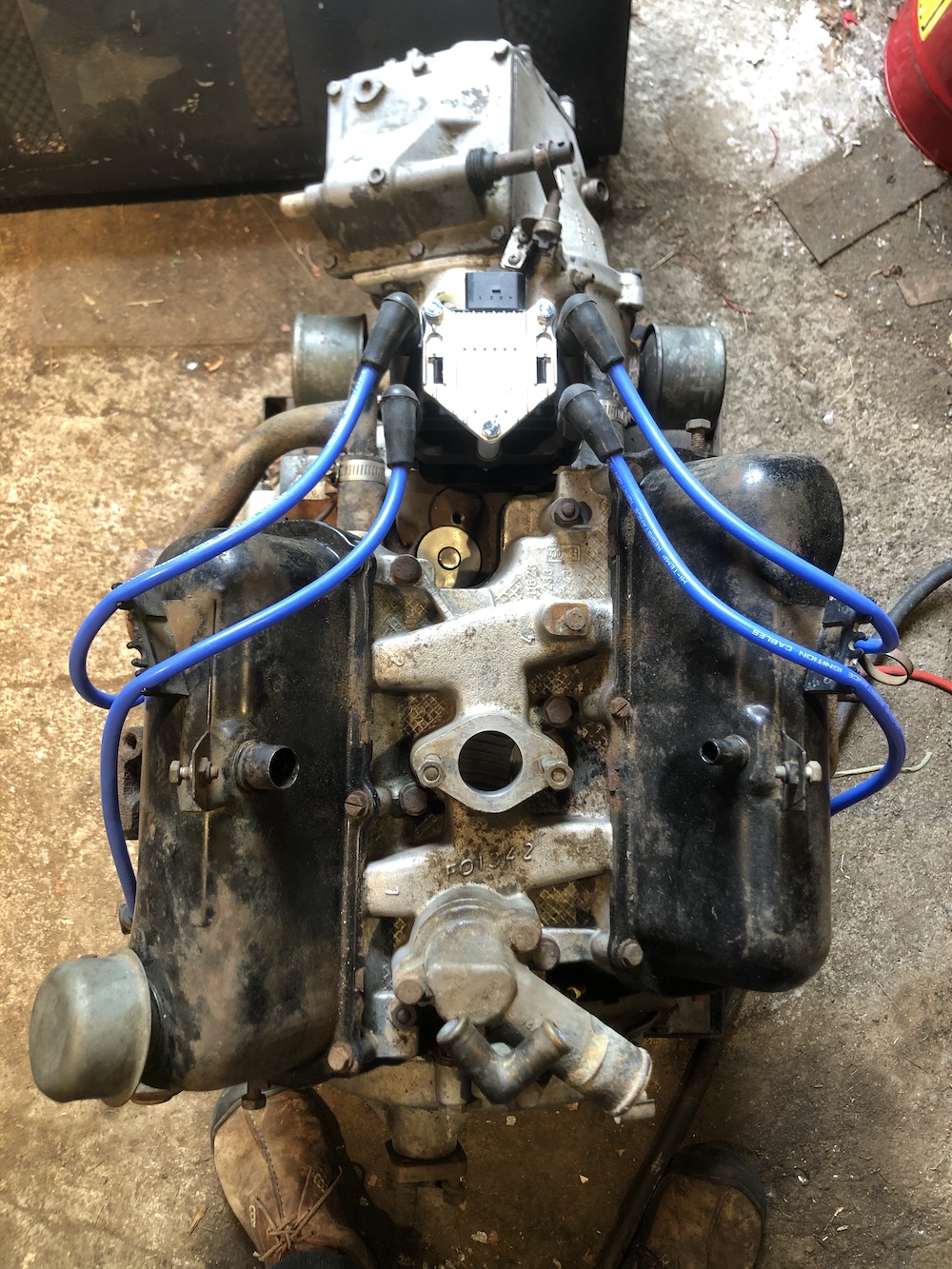
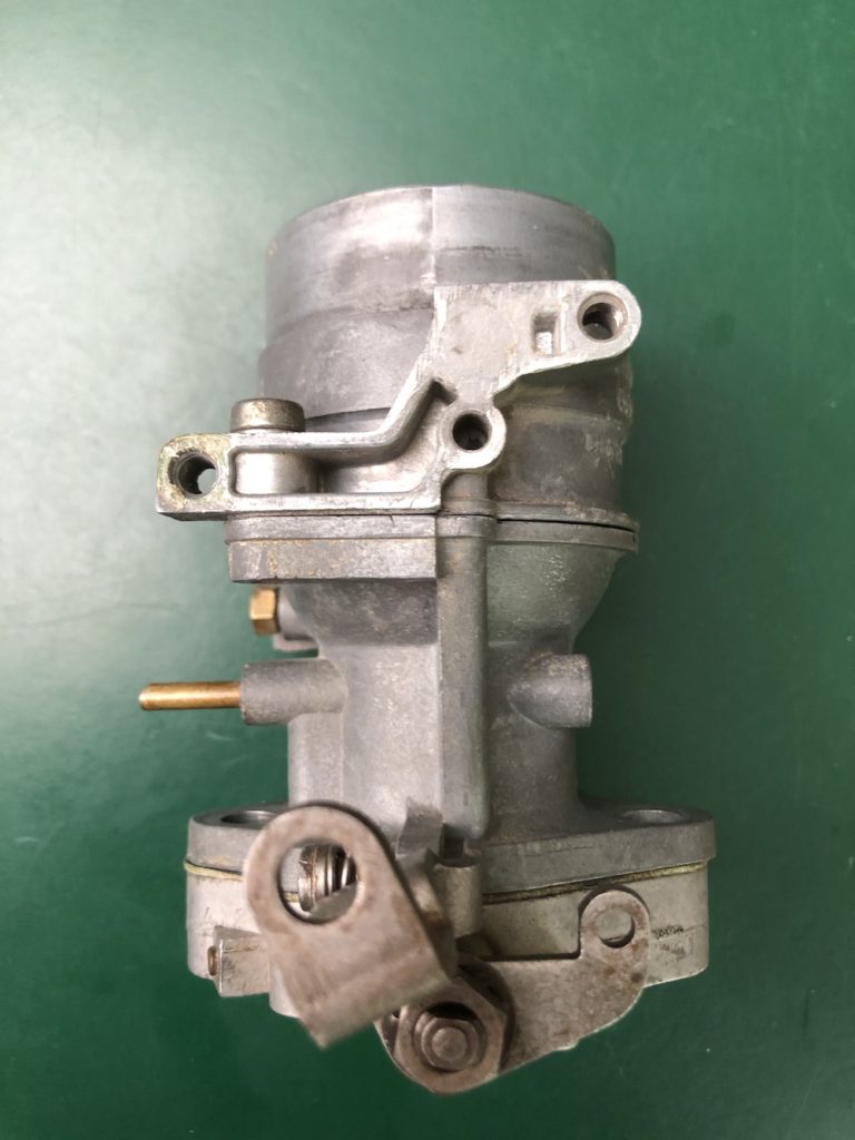
I chose to re-use the current Solex 28/32 PDSIT-4 carburetor rather than purchase a new throttle body. The carbs role to meter and deliver fuel will now be done by the fuel injectors, so the carb only needs to function as a throttle plate and provide the ECU with the throttle position.

I stripped down the existing carb by removing the fuel bowl, automatic choke and venturi and then used epoxy to fill any unneeded fuel or air passages.

Stripped Solex Carb, throttle linkage side. The threaded mounting holes at the top are for the automatic choke which I am reusing for the TPS sensor.

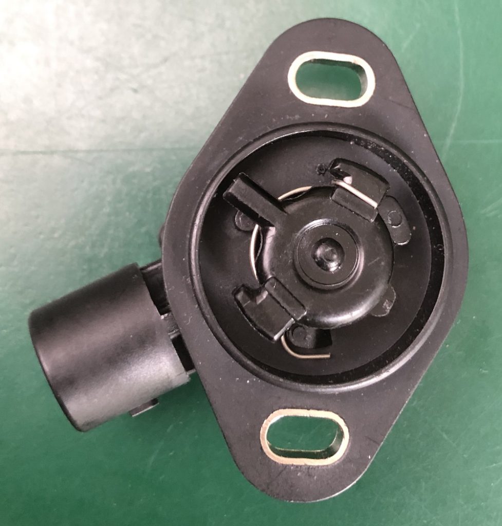
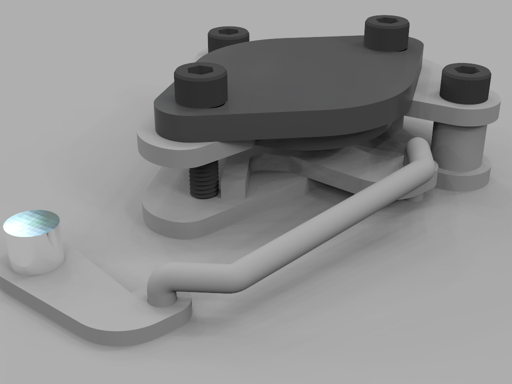
The Throttle Position Sensor (TPS) is a potentiometer that rotates the same ~90 degrees as throttle plate. The position is then read by the ECU. The task is to interface the current throttle movement to the TPS which is normally connected directly to the throttle shaft on the opposite side to the cable/linkage. On the Solex the plate turns the opposite direction to the TPS I have (from a Honda throttle body $10), so it has to mount on the same side as the linkage (or geared to the shaft) . Space is also very limited around the manifold mounted carb.

Throttle Position Sensor – Inside

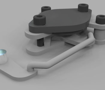
There are existing threaded mounting holes where the old choke was that I can use to attach the TPS. I designed a mount and lever system that uses the choke lever on the throttle shaft.

The existing throttle lever (lower left) to TPS (top plate) mount and linkage. Only critical detail has been modeled and the bent tabs on the lever are shown flat. The lower bolt intentionally has no spacer to clear the lever.
Assembly installed. Still needs some means of retaining the linkage. The linkage, salvaged from the fuel level float, is 2.5mm, which is again an uncommon size.

Retrospect:

Milling: I was very pleased with the milling now that I have the feeds and speeds dialed in. The dimensions of the holes were slightly small which means I probably have a calibration issue with grbl. I had my doubts about routing a 4.7mm hole with a 3.175mm mill. It works without air clearing but does regrind some chips. I am not doing finishing passes as the double stick mounting tape I’m using can’t take the force after it’s cut free from the sheet.

Design: Version 1 worked as planned and I didn’t have to redesign or recut anything. The full range of motion was just possible with the design, so I should have rotated the lever another 5 degrees counter clockwise. 3003 aluminum is too soft (“tends to be gummy when machined“) for tapping and just kind of smears into a badly formed thread. Next time I’ll use brass or steel press fit inserts. The tapped holes on the carb were metric but done in the 60’s before there were standard sizes, so they are an odd M5x0.75; I retapped these holes to M5x0.80 without losing much integrity. I should have modeled the full throttle lever as it is very close to the lower low-profile bolt for the TPS (there is another lever on the opposite side of the throttle shaft which I may use instead). This is a temporary solution just to get the system to work and then I’ll redesign the entire inefficient intake manifold.

Overall success! On to other components…

quarinjection

Quarinjection Ignition

  • May 30, 2020July 1, 2020
  • by Christian Stanton

The ignition coil generates spark and the distributor distributes it to each spark plug. The distributor also varies the timing of the spark based on the speed of the engine (via a set of centrifugal weights) and the load / requested speed of the engine (via the vacuum advance).

The ECU will now control the timing of the ignition, so I only need to generate a spark and get it to the right spark plug. Modern EFI no longer uses the mechanical distributor but individual coils to deliver spark. You can use one coil for each plug or one coil for two plugs (wasted spark).

Neutering the distributor: It made sense to put the coil pack in the same place that the old distributor was located but first I had to eliminate the distributor. It can’t just be removed as the shaft also drives the oil pump.

I cut the distributor housing at the flange and shortened the shaft to sit slightly below the surface of the housing. The lower shaft is supported by an oil pressure bearing. The shaft is thrust downward by the gear geometry and there is an axial bearing surface on the gear. There is a bushing in the top of the distributor housing which I felt was unnecessary now that there is little stress on the shortened shaft.

I’ll fabricate a cover and gasket for flange.

Spark source: I needed a coil that supported 4 cylinders and had a built in igniter. The igniter isolates the high voltage circuit and provides a low voltage interface to the ECU. I chose an ignition pack from 1998-2001 Volkswagen Golf for $15.

I fabricated a mount from sheet steel to locate it near the old distributor location.

Spark delivery: I thought I was going to be able to reuse the ignition wires, but the plugs on the coil are different. The most cost efficient way to replace them was to buy a set of VW/Audi wires ($18) that were compatible with the coil pack and replace the spark plug ends with the correct plug socket ($7). Although there are specialized crimpers, you can get away with some artful work with needle nose pliers. The core is just folded back over the wire.

Ready to be hooked to the ECU!

You can see the top of the distributor flange and shaft just below the coilpack.

quarinjection

Quarinjection Fuel Pump

  • May 29, 2020July 1, 2020
  • by Christian Stanton

Modern fuel injection systems run at ~45PSI, much higher than the ~4PSI supplied by the existing mechanical pump. The easiest solution would have been an external pump hooked to the existing fuel line but this wound up more expensive than using a common submerged in-tank pump.

The existing Sonett fuel tank sits directly behind the driver and is an unusual shape for a tank. It is tall and narrow rather than flat.

The tank is ~14″ deep. After a lot of research and cost optimization later… a Chevy 1500/2500/3500 fuel pump from 1997-2000 has the correct size and fuel layout. It is an unregulated pump with a return and vent line with a roll-over valve and correct depth. The supply volume and pressure will work for the regulator and injectors I’m using. As a bonus it includes a fuel level sensor. All for $28! (see below)

The shape of the top of the tank is too narrow to fit the mounting hole for the pump and there is very limited clearance on top of the tank, so I had to recess a flange into the tank.

DO NOT WELD FUEL TANKS! (without knowing exactly what you are doing!). This tank was dry for 15 years and washed out with water based degreaser. If I had any doubt I would have filled the tank with water up to the part I was welding.

Lesson learned: After a bit of ugly MIG welding (and I ground the welds which was a mistake and then re-welded them which was another mistake), The welds were porous and would not seal up. I resorted to a coating POR-15 fuel tank sealer inside and out to seam seal the welds.

Designing the mount: Normally these pumps have a formed flange and a twist lock retaining ring. This is not something that is easily sourced without buying an entire fuel tank. (although I found something close here) I used a design used for other flange mounts with a split internal ring with captured nuts and an external ring to retain the pump. A flat flange seal (below in white) seals the pump to the tank.

Design for Fuel Pump Mount

Fail/Revise/Repeat: I built a split “C” ring of sheet steel and welded M5 captured nuts to it. The gauge on the steel was too light and the M5 about as small as I could weld with MIG. After installation, I realized that the large flat flange seal would not seal up with the amount of pressure that I could torque the screws to and the gap in the “C” ring left part of the flange unsupported. Lesson learned: A small footprint seal (like an o-ring) works better with low pressure flanges and non-machined surfaces.

I looked at how the original seal worked. It is a sleeve that fits the diameter of the pump with a compressible o-ring-like seal at the top. The pump hat has a second step that provides a small edge for a sealing surface. The seal did not come with the pump, so I had to source one (OEM was cheapest…$13).

OEM Fuel Pump Seal

I redesigned the inner ring in aluminum and used rivet nuts to provide the threads for the retaining bolts. The inner radius of the ring had to function as the outer sealing surface, so I split the thickness around two of the rivet nuts to provide half rings I could assemble inside the tank. Lesson learned: rivet nuts will distort aluminum! …I had to tediously bend the ring back to round.

New inner mounting ring with split, before rivet nuts

Final Assembly/Retrospect: During the final assembly, I used Permatex Motoseal to seal the inner ring to the tank and the threads (do not use RTV where permanently exposed to fuel!). The existing fuel level float was removed (it was broken anyway) and the one on the new pump altered to reverse the float to clear the inside of the tank. The range for fuel sensor will be reversed but I don’t plan on driving the fuel gauge directly. The original fuel feed at the bottom of the tank was soldered shut.

There was way too much fettling with this assembly! I had to manually correct for sloppy work (or sloppy corrections to good work). The inexpensive pump wound up being more expensive than buying one which included the seal and electrical plug. Ultimately, the design got there and it will work.

Final Pump Mount (Sealed!)
Top electrical connections are left:fuel pump and fuel level (combined) and right: tank pressure (for emissions, unused in this application).
Bottom connectors are left: fuel feed, center: vent and right: fuel return.

quarinjection

Quarinjection Project

  • March 31, 2020July 1, 2020
  • by Christian Stanton

After having an assumed case of Covid-19 early on (in March) and then work projects going on hold, I needed a project I could work on daily to keep me sane.

I was cleaning my tiny shed and re-discovered 2 Ford Taunus/Cologne V4 engines from old SAAB projects. One is a 1.5L from a 1968 Saab 96 and the other is a 1.7L from a 1974 Sonett.

I spent a few evenings getting the 1.5L to run. Dead simple, just 12v to starter and coil and a hose to a fuel supply.

While that amused me for a few hours, I began to think of improvements. Which led me to a something I’ve been itching to do for a while… a full modern electronic fuel injection system.

Research ensued and I determined it was feasible within a certain budget target (~$750). I started with basic principles to reduce cost (although not complexity):

  • Use an Open source EFI package
  • Use stock parts, rather than universal or hot rod parts
  • Minimal “bench” running config
  • KISS

And away we go…

Recent Posts

  • Realistic STA-2100D Restore
  • GRBL32, STM32 and other frustrations
  • CNC gets Smart(er) Servos… not
  • Quarinjection Selecting an ECU
  • Quarinjection Throttle Position Sensor

Recent Comments

    Archives

    • April 2022
    • November 2020
    • October 2020
    • July 2020
    • June 2020
    • May 2020
    • March 2020

    Categories

    • CNC
    • projects
    • quarinjection
    • stereo recap
    Theme by Colorlib Powered by WordPress